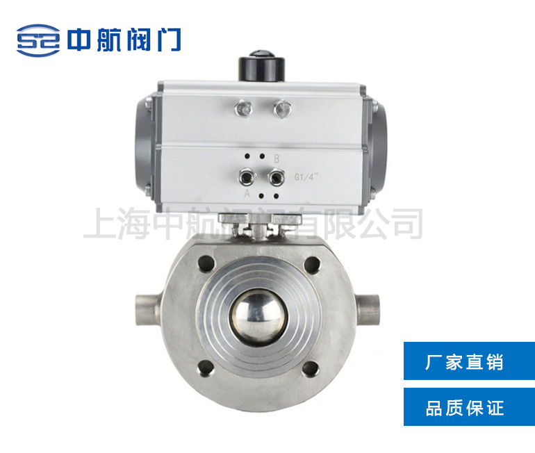
The BQ671F pneumatic insulated wafer type ball valve has good insulation and cooling characteristics. The valve diameter is consistent with the pipe diameter, which can effectively reduce the heat loss of the medium in the pipeline. Pneumatic valves are mainly used in various systems such as petroleum, chemical, metallurgical, pharmaceutical, food, etc., to transport high viscosity media with BQ671F pneumatic insulation wafer ball valve PN10~PN16 solid at room temperature. Pneumatic ball valves, due to their integral structure, are smaller, lighter in weight, leak free, and have good sealing performance compared to ordinary ball valves. The jacket is made of carbon steel pipe welded, which is more pressure resistant and firm than cast ones.
Main parts material
BQ671F Pneumatic Insulation Wafer Type Ball Valve PN10~PN16 Main Component Materials |
Serial number |
Parts name |
Material |
C |
D |
R |
1 |
Valve cover |
WCB |
ZG1C/18Ni9Ti |
ZG1Cr18Ni12M2Ti |
2 |
Gasket |
PTFE |
PTFE |
PTFE |
3 |
Valve seat |
PTFE |
PTFE |
PTFE |
4 |
Ball |
1Cr18Ni9Ti |
1Cr18Ni9Ti |
1Cr18Ni9Ti |
5 |
Valve seat |
PTFE |
PTFE |
PTFE |
6 |
Jacketed valve body |
WCB |
ZG1Cr18Ni9Ti |
ZG1Cr18Ni12Mo2Ti |
7 |
Bolt |
35 |
1Cr18Ni9i |
1Cr18Ni12Mo2Ti |
8 |
Valve stem |
1Cr13 |
1Cr18Ni9Ti |
1Cr18Ni12Mo2Ti |
9 |
Gasket |
PTFE |
PTFE |
PTFE |
10 |
Filler |
PTFE |
PTFE |
PTFE |
11 |
Bush |
PTFE |
PTFE |
PTFE |
12 |
Washer |
WCB |
ZG1Cr18Ni9Ti |
ZG1Cr18Ni12Mo2Ti |
13 |
Gasket |
35 |
1Cr18Ni9Ti |
1Cr18Ni9Ti |
14 |
Nut |
35 |
1Cr18Ni9Ti |
1Cr18N19Ti |
15 |
Connecting support |
1Cr18Ni9Ti |
1Cr18Ni9Ti |
1Cr18Ni9Ti |
16 |
Bolt |
35 |
1Cr18Ni9Ti |
1Cr18Ni9Ti |
17 |
Connection set |
35 |
1Cr18Ni9Ti |
1Cr18Ni9Ti |
18 |
Position indicator |
Plastic |
Plastic |
Plastic |
Main structure connecting size
BQ671F Pneumatic Insulation Wafer Type Ball Valve PN10~PN16 Main Structural Connection Dimensions |
Nominal diameter |
External size |
Connecting flange size |
d |
L |
L1 |
L2 |
L3 |
H |
H1 |
G |
D |
D1 |
D2 |
f |
N-Md |
15 |
14 |
35 |
140,178 |
62/75 |
150 |
170/176 |
15 |
1/2″ |
90 |
65 |
45 |
2 |
4-M14 |
20 |
19 |
38 |
140/178 |
62/75 |
160 |
175,181 |
20 |
1/2″ |
100 |
75 |
55 |
2 |
4-M14 |
25 |
25 |
42 |
140/214 |
62/91 |
190 |
180/214 |
20 |
1/2″ |
110 |
85 |
65 |
2 |
4-M14 |
32 |
29 |
50 |
164/214 |
75/91 |
210 |
215/243 |
25 |
1/2″ |
130 |
100 |
78 |
3 |
4-M18 |
40 |
38 |
60 |
164/246 |
75/101 |
230 |
225/263 |
30 |
1/2″ |
145 |
110 |
85 |
3 |
4-M18 |
50 |
48 |
70 |
190/295 |
91/112 |
250 |
248/274 |
30 |
1/2″ |
160 |
125 |
100 |
3 |
4-M18 |
65 |
64 |
95 |
210/295 |
101/112 |
270 |
258/284 |
45 |
1/2″ |
180 |
145 |
120 |
3 |
4/8-M18 |
80 |
76 |
118 |
247/395 |
112/139 |
300 |
300/326 |
50 |
1/2″ |
190 |
160 |
135 |
3 |
8-M18 |
100 |
95 |
140 |
276/478 |
127/176 |
340 |
315/370 |
70 |
1″ |
215/230 |
180/190 |
155/160 |
3 |
8-M18/20 |
125 |
112/118 |
175/195 |
348/562 |
159/206 |
360 |
375/440 |
80 |
1″ |
245/270 |
210/220 |
185/188 |
3 |
8-M18/24 |
150 |
135/150 |
210/260 |
378/724 |
176/228 |
420 |
428/500 |
95 |
1″ |
280/300 |
240/250 |
210/218 |
3 |
8-M22/24 |
Maintenance of pneumatic ball valves:
Preparation work for pneumatic ball valve before installation:
- Ensure that the installation position of the pneumatic pipeline ball valve is coaxial, and the two flanges on the pipeline should be kept parallel. Confirm that the pipeline can bear the weight of the pneumatic pipeline ball valve itself. If it is found that the pipeline cannot bear the weight of the pneumatic pipeline ball valve, provide corresponding support for the pipeline before installation.
- To confirm whether there are impurities, welding slag, etc. inside the pipeline, it is necessary to blow it clean.
- Verify the nameplate of the pneumatic pipeline ball valve, and perform several full open and full close operations on the pneumatic pipeline ball valve to confirm that the valve can function properly. Then, conduct a comprehensive inspection of all details of the valve to ensure that it is intact and undamaged.
- Remove the protective covers at both ends of the valve, check if the inside of the valve body is clean, and clean the inner cavity of the valve body. As the sealing surface of the pneumatic pipeline ball valve is spherical, even small debris may cause damage to the sealing surface.
Installation of pneumatic pipeline ball valve:
- Any section of the pneumatic pipeline ball valve can be installed at the upstream end, and the handle pneumatic pipeline ball valve can be installed at any position in the pipeline. If the pneumatic pipeline ball valve is equipped with an actuator (such as a gearbox, electro-pneumatic actuator), it must be installed vertically, and the inlet and outlet of the valve should be in a horizontal position.
- Install a sealing gasket between the flange of the pneumatic pipeline ball valve and the pipeline flange according to the pipeline design requirements.
- The bolts on the flange need to be tightened symmetrically, step by step, and evenly.
- If the pneumatic pipeline ball valve adopts pneumatic or electric actuators, complete the installation of the air source and power supply according to the instructions.
|